.png)
Network Layer: Computer Networks Class Notes
- Jun 7, 2022
- 23 min read
Updated: Oct 22, 2022
Mobiprep has created last-minute notes for all topics of Computer networks to help you with the revision of concepts for your university examinations. So let’s get started with the lecture notes on Computer networks.
Our team has curated a list of the most important questions asked in universities such as DU, DTU, VIT, SRM, IP, Pune University, Brief the functions of network layer.
Manipal University, and many more. The questions are created from the previous year's question papers of colleges and universities.
difference between logical addressing and physical addressing.
what are the different methods used to convert ipv4 to ipv6.
what are the protocols used to map logical address to physical address.
what are the protocols used to map physical address to logical address.
what is message forwarding? Explain the message forwarding techniques.
difference between distance vector routing and link state routing.
explain border gateway protocol (bgp) in detail along with its working.
what is the difference between packet switching and circuit switching?
what are the difference between static and dynamic ip addressing?
Network Layer
Question 1) Brief the functions of network layer.
Answer) The network layer is responsible for the delivery of data packets from source to destination. It ensures that the data packet is received by the receiver. The other responsibilities of the network layer are:
1. Logical addressing
The network layer assigns an address to the network device. It is also known as IP address. This address is used to uniquely identify a device within a network.
2. Routing
The network layer is responsible for routing the data packets from source to destination. Routing involves selecting the correct path for the data packets to reach the destination.
3. Fragmentation
Fragmentation is the process of dividing the data packets into multiple blocks called fragments. This is done when the size of the datagram is greater than the MTU (Maximum Transmission Unit).
Question 2) Explain logical addressing and its types.
Answer) The logical address is also called the IP address. It is the address assigned by the network layer to a device so that it can be uniquely identified within a network. No two devices in a network can have the same IP address. The IP address has two parts: Host ID and Network ID. The network ID is used to identify the network to which the device belongs. The Host ID is used to uniquely identify the device in a network.
The logical addressing is of two types:
a. Classful addressing
In classful addressing, the total address space is divided into many classes. Each class
consists of different number of bits allocated for network ID and host ID.
The IPv4 address is divided into 5 classes. They are:
Class A
It is used for very large organizations.
Here, 8 bits are used to represent network ID, and 24 bits are used to represent host ID.
2. Class B
It is for mid-size organizations.
Here, 16 bits are used to represent network ID, and 16 bits are used to represent host ID.
3. Class C
It is designed for small organizations with small number of hosts and routers.
Here, 24 bits are used to represent network ID, and 8 bits are used to represent host ID.
4. Class D
It is assigned for multicasting. i.e. Each address here is used to define one group of hosts on the internet.
5. Class E
The addresses in class E of IPv4 addressing are reserved for future use.

b. Classless addressing
In classless addressing, the address space is not divided into classes. There are no restrictions on host ID and network ID. Hence, this method is more practical and useful than classful addressing.
Question 3) Difference between logical addressing and physical addressing.
Answer)
Logical addressing | Physical addressing |
The logical address is assigned by the Internet Service Provider (ISP) | The physical address is assigned by the device manufacturer. |
It is also known as IP address | It is also known as MAC address |
The IP address of a device changes depending on the network to which it belongs. | The physical address of a device cannot be changed. It is assigned during the device manufacturing. |
The logical address is used by the network layer. | The physical address is used by the datalink layer. |
The logical address is represented in decimal form. | It is represented in hexadecimal form. |
The logical address consists of 32 bits or 128 bits.The physical address consists of 48 bits. | The physical address consists of 48 bits. |
The logical address is divided into 4 parts (each of one byte length) | The physical address is divided into 6 parts (each of one byte length) |
Example: 192.168.1.1 | Example: 42:87:FF:AE:00:11 |
Question 4) Difference between ipv4 and ipv6.
Answer)
IPv4 | IPv6 |
The IPv4 address is a 32 bit address | The IPv6 address is a 128 bit address |
Address space is small | Address space is large. |
The address space can accommodate 232 devices. | The address space can accommodate 2128 devices. |
Includes unicast, multicast and broadcast addresses. | Includes unicast, multicast and anycast addresses. Does not include broadcast address. |
It is represented in dotted decimal notation. | It is represented in hexadecimal notation separated by colons. |
Packet flow identification is not available in IPv4 | Packet flow identification is available in IPv6 using the flow label in IPv6 header |
IPv4 header contains options field and checksum field | IPv6 header does not contain options field and checksum field. |
Example: 192.168.1.2 | Example: ABCD:EF12:1243:0000:1786:FFFF:EFE1 |
Question 5) Explain the fields in the ipv4 header with diagram.
Answer) The IPv4 header is 20 to 60 bytes long. It should have a minimum length of 20 bytes. The structure of the IPv4 header is shown in the diagram given below:

IPv4 HEADER FIELD
1. VER (Version)
It is a 4-bit field.
It defines the version of IP protocol (IPv4 or IPv6).
2. HLEN (Header Length)
It is a 4-bit field.
It defines the length of the datagram header in 4 byte words.
If length of the header is 20 bytes, the value in this field will be 5 (5 x 4 = 20).
3. SERVICE
It is 8 bit field.
The first 3 bits are called Precedence Bits. The Precedence bits define the priority of the datagram when congestion occurs.
The next 4 bits define the TOS (Type of Service)
Only 1 of the 4 bits is set at a time to define the Type of Service.
Different programs request different types of service.

The last bit is not used.
4. TOTAL LENGTH
This field defines total length of the datagram including header in bytes.Length of data = total length – header length
5. IDENTIFICATION
It is a 16-bit field.
It helps to identify the fragments which belong to the same datagram. The identification field is the same for all the fragments of the same datagram. It helps in reassembly of the fragments at the receiver.
6. FLAGS
It is a 3-bit field.
The first bit is reserved.
The second bit is called Do Not Fragment (DF). If DF=1, the datagram should not be fragmented. If DF=0, the datagram is fragmented.
The third bit is called More Fragment (MF). If MF=1, it means that the current datagram is not the last fragment. If MF=0, the current datagram is the last or only fragment.
7. FRAGMENTATION OFFSET
It is a 13-bit field.
This field defines the relative position of the fragment with respect to the whole datagram.
8. TIME TO LIVE
It is an 8 bit field.
This field is used to control the maximum number of hops (routers) visited by the datagram. When the source sends the datagram, it sets a value in this filed. Each router processes the datagram and decrements this number by 1. This limits the lifetime of a datagram.
If this field is not present, the datagram may travel between two or more routers for a long time without getting delivered
9. PROTOCOL
It is an 8-bit field.
It specifies the final destination protocol to which this datagram is delivered (Higher level protocols such as TCP, ICMP, UDP, IGMP).

10. HEADER
It is a 16-bit field.
This field is used to detect errors in the header.
11. SOURCE ADDRESS
It is a 32-bit field.
It defines the IPv4 address of the source.
12. DESTINATION ADDRESS
It is a 32-bit field.
It defines the IPv4 address of the destination.
13. OPTIONS
The Options field can have a maximum of 40 bytes. It is optional.
Question 6) Explain the fields in ipv6 header with diagram.
Answer) The structure of the IPv6 header is given below:

HEADER FIELDS
1. Version
It is a 4-bit field
It defines the version of the IP protocol. (IPv4 or IPv6)
2. Priority
It is a 4-bit field.
It defines the priority of the datagram with respect to traffic congestion.
3. Flow label
It is a 3 byte (24-bit) field.
Flow is a sequence of packets that share the same characteristics (same path, same resources.
Flow label is used to speed up the processing of a packet by a router. The flow table contains the address of the next hop.
The flow label is used for transmission of real time audio and video.
4. Payload length
It is a 2-byte field.
It defines the length of datagram excluding the header.
5. Next header
It is an 8-bit field.
This field contains the address of the next datagram header.
6. Hop limit
It is an 8-bit field.
This field is used to control the maximum number of hops (routers) visited by the datagram. When the source sends the datagram, it sets a value in this filed. Each router processes the datagram and decrements this number by 1. This limits the lifetime of a datagram.
7. Source address
16-bytes
It contains the IP address of the source.
8. Destination address
16-bytes
It contains the IP address of the destination.
Question 7) What are the different methods used to convert ipv4 to ipv6.
Answer) The different methods used to convert IPv4 address to IPv6 address are:
DUAL STACK
A Dual stack network can be installed with IPv4 and IPv6 addresses configured to its interfaces pointing to the network of relevant IP scheme. The Dual stack router can communicate with both IPv4 and IPv6 networks. It enables the hosts with IPv4 or IPv6 address to communicate with the server without changing their IP address.

2. TUNNELING
This method is used when the two computers using IPv6 want to communication with each other and the packet must pass through a region that uses IPv4. Here, the IPv6 packet is encapsulated in a IPv4 packet when it enters the IPv4 region (or tunnel).

3. HEADER TRANSLATION
This method is used when the source uses IPv6 and the destination uses IPv4 or vice versa. Here, the IPv6 header is translated into IPv4 header or vice versa.

Question 8) Explain network address translation and its types.
Answer) Network address translation enables the user to have a large set of addresses internally and one, or a small set of addresses externally.
The private addresses need not be unique in the internet. Because the private addresses are visible only inside the organization. The NAT router translates the private address into the global NAT address. All outgoing packets go through the NAT router, which replaces the source address in the packet with the global NAT address. All incoming packets pass through the NAT router, which replaces the destination address with the appropriate private address, obtained from the NAT translation table.
NAT table contains only two columns:
the private address
the external address (destination address of the packet)

TYPES OF NAT
STATIC NAT
In static NAT, one private address is mapped to one Public IP address and this address does not change. It is expensive. IP addresses are wasted in this method.
DYNAMIC NAT
In dynamic NAT, mapping of Private IP address to Public IP address is dynamic. The router maps the Private IP to one of the available IP address from the pool of Public IP addresses. This method is very expensive. But, the IP addresses are not wasted.
PAT (Port Address Translation)
In this method, the port numbers are used to map traffic from specific hosts on the network. Here, each private address is mapped to a public IP address and attached to some unique port number. Using this method, many internal hosts can be handled with a single public IP address.

PORT FORWARDING
It allows network administrators to use one IP address for all external communications on the Internet while dedicating multiple servers with different IPs and ports to the task internally. Port forwarding technique is explained using the diagram given below:

Question 9) What is meant by fragmentation? Why is it needed?
Answer) Fragmentation is the process of dividing the data packets into multiple blocks called fragments. This is done when the size of the datagram is greater than the MTU (Maximum Transmission Unit).
The limit in the size of datagrams that can be processed by a network is called Maximum Transmission Unit (MTU). A datagram larger than the MTU cannot be transmitted directly through the network. The datagram has to be broken down into small fragments, so that the size of the datagram becomes smaller than the MTU. The transmitted data fragments are reassembled at the receiver.
Question 10) What are the protocols used to map logical address to physical address.
Answer) The following protocols are used to map the logical address to physical address:
a. ARP
When the source needs to send a packet to destination and it knows its IP address, it looks into its ARP cache for the destination’s MAC address. If the receiver IP is not mapped to any MAC address, the sender broadcasts a message asking the MAC address of the computer that has the specific IP address. The destination replies to this message with its MAC address. Once the sender receives the destination MAC, it stores it in the ARP cache.
The ARP cache is a table that stores the IP to MAC address associations.
ARP MESSAGES
1. ARP REQUEST
The ARP request is broadcast in nature, but the ARP reply is unicast.
The MAC address of the device is kept null because the source has requested for it.
2. ARP REPLY
The target machine (or destination) replies to the ARP Request. The reply is unicasted to the sender. The ARP reply contains the receiver’s MAC address.
b. PROXY ARP
This method is used to create sub-netting effect to ARP. Proxy ARP acts on behalf of a set of hosts. When running a proxy ARP, if an ARP request is received for the IP address of one of its hosts, it sends its own MAC address instead of the host’s address. After it receives the actual IP packet, it sends the packet to an appropriate host or router.
Question 11) What are the protocols used to map physical address to logical address.
Answer) The following protocols are used to map physical address to logical address:
a. RARP (Reverse Address Resolution Protocol)
RARP is a datalink layer protocol. Two messages are used in the RARP protocol. They are RARP request and RARP reply.
RARP request
The RARP request is broadcasted in the network by the RARP client (the system which needs its own IP)
RARP reply
RARP server replies with the corresponding IP address. The server has all the physical addresses mapped to the IP address in table form.
Broadcasting of RARP is done at data link layer. This increases the implementation cost. RARP provides only the IP address, but not subnet mask, default gateway etc.
b. BOOTP
The BOOTP protocol is the successor of RARP protocol and predecessor of DHCP protocol.
BOOTP is similar to RARP, but the Server can be in another network. It is a client server model. BOOTP uses a static database to store the mapping of MAC address to IP address, while DHCP uses a dynamic database. The entries in the database must be entered manually.
BOOTP request is broadcasted in the network. As the BOOTP request cannot be broadcasted into another network, there is a device called relay agent which knows the IP address of the server. It unicasts the BOOTP request to the server.
c. DHCP (Dynamic Host Configuration Protocol)
In DHCP, the database which contains the mapping of MAC address to the corresponding IP address is dynamic. DHCP maintains a pool of IP addresses.
When the DHCP server receives a DHCP request, assigns one of the IP addresses from the pool for a period of time unless some reservations are made. The entry is added in the dynamic database. The DHCP server first checks in its static database if the requested physical address exists in the permanent database. If the physical address does not exist in the database, it assigns an IP address dynamically.
Question 12) What is ARP? What are ARP messages?
Answer) ARP – Address Resolution Protocol
ARP is a protocol which is used to map the IP address to the corresponding MAC address. The working of the ARP protocol is given below.
When the source needs to send a packet to destination and it knows its IP address, it looks into its ARP cache for the destination’s MAC address. If the receiver IP is not mapped to any MAC address, the sender broadcasts a message asking the MAC address of the computer that has the specific IP address. The destination replies to this message with its MAC address. Once the sender receives the destination MAC, it stores it in the ARP cache.
The ARP cache is a table that stores the IP address to MAC address associations.
ARP MESSAGES
a. ARP REQUEST
It consists of the sender’s physical address and IP address and the receiver’s IP address. The receiver’s MAC address field is filled with 0’s.
Destination address of the packet is broadcast address.
b. ARP REPLY
The target machine (or destination) replies to the ARP Request. The reply is unicasted to the sender. The ARP reply contains the receiver’s MAC address.
Question 13) What is ICMP? Explain its usage
Answer) ICMP is a transport layer protocol that is used along with the TCP/IP protocol. ICMP is considered as an integral part of the TCP/IP protocol suite. ICMP provides error reporting mechanism to the IP protocol. It only reports errors, but it does not correct them. The ICMP data packet consists of an 8 byte header and a variable size data section. ICMP reports the information on network connectivity, and the speed of data relay between the source and the destination.
The ICMP protocol provides the following services:
Error Reporting
Congestion Reporting
First-hop router Redirection
Question 14) What are the ICMP messages?
Answer) The ICMP messages are of two types. They are:
Error reporting messages
Query messages
ERRORS MESSAGES
Destination unreachable
This error is generated when the router can’t route the datagram or when the host can’t deliver the datagram.
Source quench
This message is used to add flow control to IP protocol. It is generated when a router discards the datagram due to congestion. The Source Quench message indicates that the source should slow down the sending process.
Time exceeded
This error message is generated when datagram is discarded due to expiration of time to live.
Parameter problems
This error is generated when there is ambiguity or missing value in any field in the datagram.
Redirection
The redirection message is sent to the host to update its routing table whenever there is change in the network.
QUERY MESSAGES
The query messages are used to diagnose some problems in the network.
Echo request and reply
The echo request and echo reply are used to check whether the two systems (sender and receiver) can communicate with each other.
Timestamp request and reply
Timestamp request and reply are used to determine the round trip time needed for an IP datagram to travel between two machines.
Address mask request and reply
This message is used to obtain the address mask of the router.
Router solicitation and advertisement
When a host sends router solicitation message, all the routers that receive this message broadcast their routing information using the router advertisement message.
Question 15) Explain the header format of ICMP in detail.
Answer) The ICMP header is of 8-byte in length. The first 4 bytes of the header have fixed format. But, the last 4 bytes are dependent on the type/code of that ICMP packet. The ICMP header is shown in the figure given below:

Header Fields
Version - This field is always set to 4.
Internet Header Length- This field represents the length of the header in 32 bit words.
Type of Service - This field should be set to 0, as this is the only legit setting according to RFC 792 - Internet Control Message Protocol.
Total Length - This field represents the total length of the header and data portion of the packet, counted in octets.
Identification, Flags and Fragment offsets - Ripped from the IP protocol.
Time To Live - This field represents how many hops this packet can survive.
Protocol - This field shows the version of ICMP being used (should always be 1).
Header Checksum - Checksum is used to provide error control mechanism.
Source Address - This field tells the address of the sender or source of the packet.
Destination Address - This field tells the address of the destination or receiver.
Type - The type field contains the ICMP packet type. For example, ICMP destination unreachable packet has the type field set to 3.
Code - All ICMP packet types can contain different codes as well. For example, the ICMP Destination Unreachable (type 3) can have 0, 1, 2, 3, 4 or 5 code set. Each code has a different meaning in that context. This field is 8 bits in length, total.
Checksum - The Checksum is a 16 bit field containing a one's complement of the ones complement of the headers starting with the ICMP type and down.
Question 16) What is IGMP? Why is it needed?
Answer) IGMP – Internet Group Management Protocol
IGMP is a network layer protocol that is used along with the IP protocol. It belongs to the TCP/IP protocol suite. The IGMP protocol is used for multicasting and unicasting by the IP protocol. IGMP is not a multicast routing protocol, but it manages group membership for multi-casting. In other words, IGMP is a group management protocol. Routers use IGMP protocol to manage and maintain multicast group members. IGMP packets are encapsulated in IP data packets for transmission.
It helps the multicast router to create and update a list of loyal member related to each router interface. Each router or host can use IGMP protocol to create and maintain the list of members of the group.
Question 17) What are the IGMP messages?
Answer) There are three types of messages used by IGMP. They are:
Query message
Membership report
Leave report
Routers send query messages to the group members to check their online status. The members reply to the router with report messages.
Query Message
The query messages are sent by the router to find out which devices are attached to which multicast group.
Membership Report
The membership report is sent by the host to the router. By sending the membership report twice, the host or process can join a group.
Leave Report
If a host or a process wants to leave a group, it sends the leave report the router.

Question 18) How does the IGMP protocol work? Explain.
Answer) The IGMP protocol operates between a host and a multicast router. A multicast router has a list of multicast addresses of the groups with at least one loyal member in the network. For each group, there is one router that distributes the multicast packets destined for that group.
The query messages are sent by the router to find out which devices are attached to which multicast group.
Joining a group
A process can join the group by sending IGMP membership report twice, one after the other (in case one is lost or damaged, the other replaces it).
Leaving a group
A process sends a leave report, when it is not interested in a specific group. The router then sends the special query message to all its members to check any other node wants to join the group. If no members reply back, the group is purged.

Question 19) What is message forwarding? Explain the message forwarding techniques.
Answer) Message forwarding is the function of network layer. It is the process of sending the data packet is placed in its route to the destination. When a router receives a data packet, it passes the data packet to the next hop in the route from the source to destination. This is called message forwarding. For the router to perform message forwarding, the router must have a routing table.
There are five different message forwarding techniques:
a. Next hop method
In this method, the routing table contains only the address of the next hop in the route from source to destination. This method reduces the size of the routing table, as it contains only the address of the next hop.

b. Route method
In this method, the entire route from the current router to the destination is mentioned in the routing table. This is shown in the diagram given below:

c. Host specific method
In this method, there is an entry for every host in the routing table.
d. Network specific method
In network specific message forwarding, the routing table consists of only one entry for a network, instead of every node in the network. This simplifies the routing process.
The routing tables of host-specific and network-specific message forwarding are shown below:

e. Default method
This method is used to simply the routing process. Let host A be connected to a network with two routers. Router R1 routes the packets to hosts connected to network N2. However, for the rest of the Internet, router R2 is used. So instead of listing all networks in the entire Internet, host A can just have one entry called the default (normally defined as network address 0.0.0.0).

Question 20) Define routing table and explain its types.
Answer) The routing table is the list of all network routes that are known. It is stored in the RAM of the device. Routers use routing tables to determine the path in which the packet has to be sent.
An example of a routing table is given below:

The routing table consists of the following fields:
Destination network - address of the destination node
Next hop - address of the next node to which the data has to be sent in order to reach the destination finally.
Interface - it is the name of the interface that connects the current node and the next node.
Types of routing table
Static routing table
In a static routing table, the routes are updated manually. If the network changes, the routing table entries are not updated automatically. The routes have to be modified manually.
2. Dynamic routing table
In a dynamic routing table, the routes are updated automatically. If there is any change in the network, the routing table is modified automatically according to the network. It is more complex.
Question 21) What are the different types of routing?
Answer) There are three types of routing. They are:
a. Static routing
It is a process in which the routes are manually added to the routing table.
b. Dynamic routing
Dynamic routing makes automatic adjustment of the routes according to the current state of the route in the routing table. Dynamic routing uses protocols to discover network destinations and the routes to reach it. Automatic adjustment will be made to reach the network destination if one route goes down.
RIP and OSPF are dynamic routing protocols.
c. Default routing
In default routing method, the router is configured to send all packets towards the next hop. It doesn’t matter to which network the packet belongs, it is forwarded out to router which is configured for default routing. It is generally used with stub routers. A stub router is a router which has only one route to reach all other networks.
Question 22) Define distance vector routing with examples.
Answer) The distance vector routing algorithm is a dynamic routing algorithm that operates in the network layer. Each router prepares a routing table based on the distance to the neighboring routers. Each router exchanges its distance vector with its neighboring routers. Each router prepares a new routing table using the distance vectors it has obtained from its neighbors. These steps are repeated (n-2) times, where ‘n’ is the number of routers in the network. After this, the routing table becomes stable.
Example:

The routing tables of the above network before and after distance vector routing are shown below.
Routing tables of all the nodes before distance vector routing

Final routing tables (after distance vector routing)

Question 23) Define link state routing with examples.
Answer) Link state routing algorithm is a routing algorithm that operates in the network layer. Here, each node knows the entire topology of the network (list of nodes, cost, and condition of links). It uses Dijkstra’s algorithm to build the routing table.
STEPS INVOLVED
Initially, each router determines the link cost on each of its interface.
The router then advertises these costs to all the other routers in the network.
Whenever any change occurs in the network, the routers re-calculate the costs, and the costs are updated.
Each router calculates the shortest path to each destination in the network. Dijkstra’s algorithm is used to compute the shortest path.
The computation of shortest path is shown in the following example:

Question 24) Define path vector routing.
Answer) Path Vector routing is a network routing algorithm that operates at the network layer. It is used for inter-domain routing within an autonomous system. It is a unicast routing protocol. It is an extension of distance vector routing protocol. But, it does not rely on the distance to destination to provide a loop-free path. But, it relies on the path analysis. So, path vector routing protocols can be used in environments in which a consistent distance metric cannot be guaranteed.
In path vector routing, the networks are advertised in terms of the destination address and the path descriptions to reach the destination. Here, the paths are updated based on the neighbor’s paths. In path vector routing, there is a node called speaker node in each autonomous system. The speaker node creates the routing table advertises it to the speaker nodes of the neighboring autonomous systems.
BGP (Border Gateway Protocol) is an example of Path Vector Routing Protocol.
Question 25) Difference between distance vector routing and link state routing.
Answer)
Distance Vector Routing | Link State Routing |
Routers communicate with the nearby routers by advertising networks as measures of distance and vector. | Routers communicate with the nearby routers by advertising the link state information. |
Entire routing table is sent | Only the link state is sent |
Susceptible to routing loops | Not susceptible to routing loops. |
The routers do not know the entire network topology | All the routers know the entire network topology. |
Sends periodic updates of the entire routing table. | Sends triggered partial updates. |
Preferred for small and simple networks. | Preferred for large and complex networks. |
The updates are broadcasted. | The updates are multi-casted. |
Simple to configure. | Complex to configure. |
Example: RIP, IGRP. | Example: OSPF, ISIS |
Question 26) Explain rip routing protocol.
Answer) Routing Information Protocol (RIP) is a dynamic routing protocol which uses hop count as a routing metric to find the best path between the source and the destination network. It is a distance vector routing protocol. RIP uses port number 520. Hop count is the number of routers occurring in between the source and destination network. The path with the lowest hop count is considered as the best route to reach a network and therefore placed in the routing table.
Network updates are exchanged periodically. The updates are always broadcasted. Full routing tables are sent in updates. Routers always trust on routing information received from neighbor routers. This is also known as routing on rumors.

Question 27) Explain the working of OSPF protocol.
Answer) OSPF – Open Shortest Path First
OSPF is a link-state routing protocol that is used to find the best path between the source and the destination router. It is a network layer protocol which works on the protocol number 89. OSPF uses multicast address 224.0.0.5 for normal communication and 224.0.0.6 for update to designated router.
Every router contains the same information about the network. The way the router learns this information by sending LSA (Link State Advertisements). These LSAs contain information about every router, subnet, and other networking information. Once the LSAs have been flooded, the OSPF stores the information in a link-state database known as LSDB. The main goal is to have the same information about every router in LSDBs.
OSPF divides the autonomous systems into areas where the area is a collection of networks, hosts, and routers. This is done for easy management of the network.
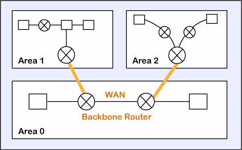
Working
The two connecting routers running OSPF on the same link creates a neighbor relationship.
The second step involves exchange of database information. After becoming the neighbors, the two routers exchange the LSDB information with each other.
The third step involves choosing the best route. Once the LSDB information has been exchanged with each other, the router chooses the best route to be added to a routing table based on the calculation of SPF.
Question 28) Explain border gateway protocol (BGP) in detail along with its working.
Answer) Border Gateway Protocol (BGP) is a standardized exterior gateway protocol designed to exchange routing and reachability information between autonomous systems (AS) on the Internet. It is a path vector routing protocol. The BGP protocol enables the Internet to function.
Each BGP speaker, which is called a “peer”, exchanges routing information with its neighboring peers in the form of network prefix announcements. This way, an AS doesn’t need to be connected to another AS to know its network prefix.
The BGP decision-making mechanism analyzes all the data and sets one of its peers as the next stop, to forward packets for a certain destination. Each peer manages a table with all the routes it knows for each network and propagates that information to its neighboring autonomous systems. In this way, BGP allows an AS to collect all the routing information from its neighboring autonomous systems and “advertise” that information further. Each peer transfers the information internally inside its own autonomous system.

Question 29) What do you understand by datagrams?
Answer) Datagrams refer to the messages that are sent over the network independently. These are independent, self-contained messages that whose arrival is not reliable. In other words, datagrams are the basic units of data transfer in packet switched network. Datagrams provide connectionless communication between the sender and the receiver. Datagrams contain the address of source and destination.
Question 30) What do you understand by virtual circuits?
Answer) Virtual circuits are used in packet switched networks. It is used to transport data from source to destination in a packet switched network. The data packets are transferred in such a way that it appears as if there exists a physical link between the source and destination. Virtual circuits provide connection oriented communication between the source and the destination nodes.
Question 31) What is packet switching?
Answer) Packet switching is a method in which the data is divided into small pieces called packets for fast and efficient data transfer. Each data packet consists of a packet header that includes the source IP address, the destination IP address, the number of packets in the entire data file, and the sequence number. The data packets are rearranged at the destination using the sequence number. Packet switching is a connectionless network switching technique. It does not require a dedicated connection between the source and destination. But, delivery of the data packets is not guaranteed. Packet switching saves channel bandwidth.
Question 32) What is the difference between packet switching and circuit switching?
Answer)
Packet Switching | Circuit Switching |
There is no physical path between source and destination. | A physical path exists between the source and destination. |
All packets in the data follow the same path. | The data packets follow different paths. |
Bandwidth has to be reserved in advance. | Bandwidth need not be reserved in advance. |
Does not support store and forward transmission. | Supports store and forward transmission. |
Data packets arrive in-order at the destination. | Data packets arrive out of order at the destination. |
Delivery of data packet is guaranteed. | Delivery of data packet is not guaranteed. |
Leads to wastage of channel bandwidth. | Channel bandwidth is not wasted. |
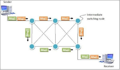
Question 33) What is message switching?
Message switching is a network switching technique where the entire message is routed from the source to the destination, one hop at a time. Each message has the source address and the destination address. Each message is transmitted independently. Message switching method was used before the packet switching method. Message switching provides connectionless communication between the source and destination. This method uses store and forward technique. i.e. the intermediate nodes store the entire message until the message reaches its destination.
Question 34) How virtual circuits are implemented?
Answer) The working of virtual circuits is explained below:
A medium is set up between the source and destination.
Resources are reserved for the transmission of packets.
Then, a signal is sent to sender to tell the medium is set up and transmission can be started. Transmission of all the packets is ensured. A global header is used in the first packet of the connection.
Whenever data is to be transmitted a new connection is set up.

Question 35) What are the difference between static and dynamic ip addressing?
Answer)
Static IP addressing | Dynamic IP addressing |
In static IP addressing, an IP address is permanently assigned to the device. | In dynamic IP addressing, an IP address is assigned only when the device is connected to the network. |
The static IP address is assigned by the network administrator. | The dynamic IP address is assigned by the DHCP server. |
The static IP address cannot be changed | The dynamic IP address cannot be changed. |
It is not secure. | It is secure. |
This method is not efficient. | This method is efficient. |
Question 36) What is subnetting?
Answer) Subnetting is the process of dividing a large network into multiple small networks. Subnetting is mainly done to avoid wastage of IP addresses in a network.
Subnetting is done by borrowing some bits from the Host ID in the IP address, and using them to identify different subnets of a network. The process of subnetting is explained in detail using the diagram given below:

Question 37) What is the difference between routing and forwarding?
Answer) Routing
Routing involves sending the data packet from the source to destination. The path from source to destination is stored in the routing table. Routing is done in the network layer. The intermediate nodes in the routing table are dynamically updated.
Forwarding
Forwarding involves sending a data packet to the next node or device in the path. It is the process of sending the data to its interface which is on the path from source to destination. The forwarding table used in the forwarding technique is static.
Question 38) What do you mean by adaptive and non adaptive algorithm?
Answer) Adaptive Routing Algorithm
In adaptive routing algorithm, the routing decisions are made based on the network topology at that particular instant of time. The routing is also based on the network traffic, and other network conditions. Here, the entries in the routing table are modified automatically based on the network changes. Adaptive routing algorithm is very complex when compared to non-adaptive routing algorithm.
Non-adaptive Routing Algorithm
In non-adaptive routing, a static routing table is used. The entries in the static routing table are manually configured. The routing decisions do not change automatically based on the network conditions. The network administrator has to manually add the routes to the routing table. Non-adaptive algorithm is very simple when compared to the adaptive routing algorithm.
Question 39) Explain multicast and broadcast routing.
Answer) Multicast routing
Multicast routing is used to send a data packet to multiple devices. Multicasting involves one sender and multiple receivers. Here, the sender sends the data to a multicast address (or group address). The multicast address is used to distribute the data to the devices in the specified multicast group.
Broadcast routing
Broadcast routing involves sending data to all the devices in the network. In broadcast networking, the data is sent to the broadcast address. The broadcast address is used to send data to all the devices in that particular network.
Question 40) What is hierarchical routing?
Answer) In hierarchical routing, the routers are arranged in a hierarchical manner. It involves hierarchical addressing. Hierarchical routing is used when the network is very large that centralization of the system becomes impossible. In such a case, the system is organized into multiple levels with many group loops connected to one another at each level.
A domain in the hierarchical routing refers to a set of networks interconnected by routers. Two or more domains might be connected to a higher level domain. A router that connects different domains are called inter-domain routers. The router that connects the devices within a network is called intra-domain router. A network of inter-domain routers forms the network backbone.
An example of hierarchical routing is given below:

The above network consists of a backbone network. Several interconnected routers are connected to the backbone network. These interconnected routers constitute a network domain.


Comments